Customer profile
A mid-sized structural steel fabrication consultancy employs a team of detailers and structural engineers responsible for maintaining a library of reusable connection templates. These templates capture standard joint configurations — beam-to-column connections, gusset plate assemblies, base plate details, and bracing systems — that the team draws on repeatedly across client projects. The group works primarily with DWG files produced in AutoCAD and compatible drafting platforms, distributing them to external fabricators as both production references and internal engineering standards.
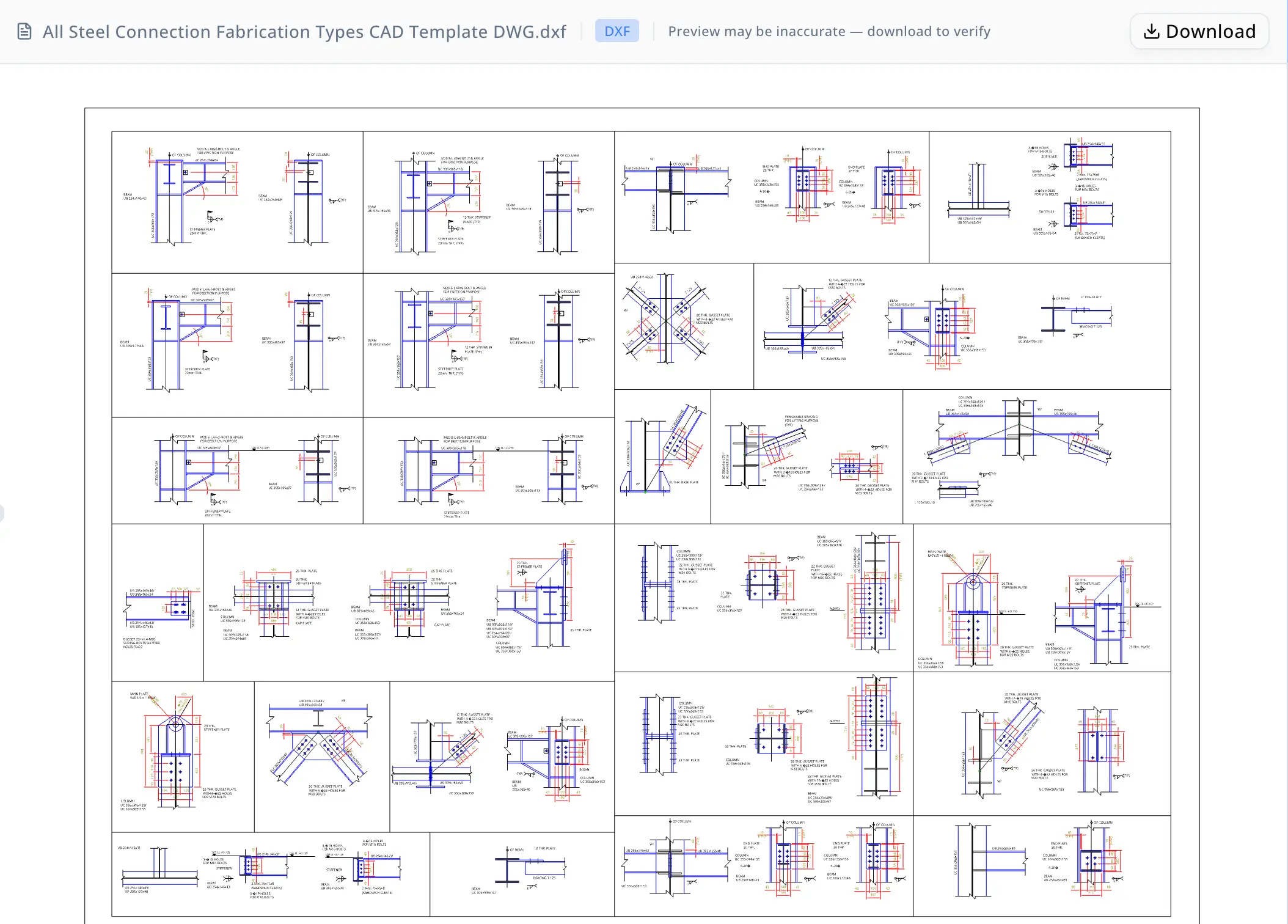
At the center of a recent engagement was a single multi-layout DWG template that had accumulated a comprehensive set of steel connection fabrication details over several project cycles. The drawing was authoritative and widely reused, but its density and the absence of any internal index made it time-consuming to navigate, interpret, and share with downstream users. The team needed a way to extract the drawing's contents systematically — not just open it in CAD.
Problem
The DWG template contained 3,487 modelspace entities organized across three layouts — Model, Layout1, and Layout2 — and totaled approximately 1.9 MB of geometry. Distributed across the drawing were 419 text labels grouped into 14 distinct spatial cluster zones. These labels annotated plate thicknesses (12 THK, 20 THK, 25 THK), bolt specifications (M16 and M20), and structural section types including UB and UC universal beams and columns.
The core difficulty was structural: none of the 14 zones carried explicit detail numbers or titles. The drawing contained at least 11 distinct connection detail types — beam-to-column joints, gusset plates, stiffener plates, cap plates, base plates, cleats, padeyes, bolt hole patterns, lifting details, removable bracing assemblies, and splice connections — but identifying each one required correlating spatial position with label content, layer assignments, and geometric context. There was no legend, no title block indexing the details, and no machine-readable summary of what the drawing contained.
Without dedicated tooling, this kind of drawing triage follows a familiar and expensive path. An engineer opens the file in AutoCAD, switches between layouts, toggles layer visibility one at a time, traces each annotation cluster back to its parent geometry, and manually builds a summary of what each region of the drawing represents. For a file of this density — nearly 3,500 entities and more than 400 text labels — that process typically consumes several hours of an engineer's time. The resulting index is usually a hand-typed list or an informal spreadsheet: undershared, difficult to update when the drawing changes, and completely disconnected from the underlying DXF structure.
Compounding the problem, external fabricators required more than the raw DWG file. Before beginning shop work, the fabricator's team needed a clear, navigable summary identifying which connection details the drawing contained and what each was for. Producing that summary manually added yet another documentation step after the inspection work was already complete.
Why now
The immediate trigger was a scheduled fabrication handoff. The team needed to transmit the steel connection template to an external fabricator within a fixed project timeline, and the fabricator's shop required a drawing summary before starting work. Without an index, the fabricator would request clarification on individual details — adding days of back-and-forth to a constrained schedule.
Beyond the immediate deadline, the team was evaluating how to standardize their broader CAD template library. Several drawing files had accumulated over the years with no consistent indexing methodology, meaning every reuse required a fresh inspection from scratch. The fabrication handoff gave the team a specific, time-bounded reason to evaluate a more systematic approach to CAD drawing documentation — one that would scale across the library, not just solve the problem for a single file.
Why energent.ai
The team had three realistic alternatives and found each inadequate for the task at hand.
Their CAD software could display and edit the drawing at full fidelity but offered no automated summarization, spatial clustering, or structured report generation. Any analysis performed inside the CAD tool still required manual interpretation and a separate documentation step — the same hours of work they were trying to avoid.
Writing a custom Python extraction script was technically feasible but required scoping the extraction logic, handling the DXF entity model, implementing a clustering algorithm, and validating the output against the source file. That investment was difficult to justify for a single drawing and would need to be reproduced or maintained for every other template in the library.
General-purpose AI tools the team had explored could discuss CAD conventions and steel connection standards in the abstract, but none could accept an actual DWG upload, parse its entity structure, and produce a spatially grounded analysis tied to real coordinates and label counts.
Energent.ai accepted the DWG file directly, ran a validated conversion and extraction pipeline, and delivered structured deliverables — without custom scripting, manual layer inspection, or specialist tooling from the team.
Workflow
Step 1: File upload and DWG-to-DXF conversion. The detailer uploaded the DWG template to energent.ai. The agent converted the file to DXF format (version AC1027) and validated the output using the ezdxf library, confirming 3,487 modelspace entities across three layouts and a file size of 1,908,830 bytes. An independent read-back verification pass confirmed the DXF was structurally valid and that entity counts matched the conversion output. This step required no configuration from the user.
Step 2: Entity and label extraction. The agent extracted all text entities from the converted DXF, capturing each label's content along with its spatial coordinates. This yielded the full inventory of 419 text labels alongside a catalogue of the broader entity mix — lines, arcs, block references, and dimension objects — and the layer structure underlying the drawing's organization.
Step 3: Spatial clustering. Using the coordinate data from the extraction step, the agent segmented the 419 labels into 14 cluster zones based on spatial proximity. Each cluster corresponded to a distinct region of the drawing, grouping annotations that pertained to a single connection detail or closely related detail set. This cluster map provided the structural foundation for the interpretation step that followed.
Step 4: Connection detail interpretation. Working from the cluster map and the label content within each zone, the agent identified 11 connection detail types: beam-to-column joints, gusset plates, stiffener plates, cap plates, base plates, cleats, padeyes, bolt hole patterns, lifting details, removable bracing assemblies, and splice connections. For each type, the agent documented associated plate thickness annotations and bolt specifications — 12 THK, 20 THK, and 25 THK plates; M16 and M20 bolts — and described the fabrication purpose of each connection.
Step 5: Markdown walkthrough. The agent generated a structured Markdown report (steel_connection_drawing_walkthrough.md) covering a step-by-step reading guide for the drawing, descriptions of all 11 detail types with practical fabrication notes, the key labels associated with each detail, and the full 14-cluster zone summary. The report was formatted for direct inclusion in a project handoff package or internal technical reference library.
Step 6: Interactive HTML dashboard. The agent produced a browser-based HTML dashboard (steel_connection_visual_dashboard.html) containing a cluster layout map of the drawing, entity type and layer count summaries, a connection-detail-to-cluster mapping table, and a searchable table of all 14 clusters with sample labels. The dashboard included an explicit caveat noting that detail groupings were inferred from spatial and label context, because the source file carried no explicit detail numbers or titles.
The entire sequence — from file upload through verified deliverables — ran within a single session.

Results
All metrics below trace directly to entity counts and structural features confirmed in the source DWG file.
- 419 text labels extracted from the DXF, each captured with spatial coordinates and organized by cluster zone.
- 14 spatial cluster zones identified and mapped across the drawing's modelspace, providing a navigable index that the source file did not contain.
- 11 connection detail types documented, each with associated plate thickness and bolt callout references drawn from the actual drawing labels.
- Two structured deliverables produced: a Markdown walkthrough formatted for fabricator handoff, and an interactive HTML dashboard suitable for non-CAD users navigating the drawing's contents.
The qualitative outcome was equally significant. Work that would typically require an engineer to spend several hours in AutoCAD — toggling layer visibility, correlating annotation clusters with geometry, and writing a separate summary document — was completed in a single agent session. The resulting documentation was more structured and complete than what the manual process typically yields, and it was immediately shareable in both Markdown and browser-based formats. The team also gained a replicable workflow applicable to other templates in their CAD library without additional scripting or specialist tooling.
Extracted detail clusters
The automated extraction found 14 text-label clusters. Some clusters are broad because the DWG places many connection details close together, so the interpretation above consolidates them into practical detail types.
| # | Labels | Bounding box [xmin, ymin, xmax, ymax] | Sample labels |
|---|---|---|---|
| 1 | 21 | [42893.6, 21663.8, 44542.1, 22894.7] | UB 254x146x31, 3-∅18 HOLES, FOR M16 BOLTS, STIFFENER, BEAM, 2 Nos. 75x75x8, UB 305x165x46, (SANDWICH CLEATS), UB 305x165x46/, UB 305x165x54 |
| 2 | 92 | [31887.3, 19754.1, 41965.8, 22830.5] | ℄ OF COLUMN, M20 & L 60x6 BOLT & ANGLE, FOR ERECTION PURPOSE, WP, UC 254x254x89, END PLATE, UB 254x146x43, UB 305x127x48, UC 305x305x118, 20 THK., COLUMN, UC 356x368x153 |
| 3 | 108 | [32373.1, 16669.5, 44506.4, 21105.3] | 12 THK. GUSSET PLATE, WITH 4-∅22 HOLES FOR, M20 BOLTS, ℄ OF COLUMN, 12 THK. PLATE, ℄ OF BEAM, BEAM, T 125, UC 305x305x137, BRACING T 125, 6-20∅, (TYP) |
| 4 | 4 | [43942.1, 18947.4, 44621.6, 19408.0] | WP, BEAM, UB 305x165x46, L 120X120X10 |
| 5 | 14 | [34188.8, 16397.7, 34974.4, 17281.8] | 25 THK. PLATE, 20 THK., STIFFENER PLATE, BEAM, 12 THK. GUSSET PLATE, UB 305x165x46, WITH 4-∅22 HOLES, FOR M20 BOLTS, COLUMN, UC 356x368x153, CAP PLATE, UC 305x305x137/ |
| 6 | 14 | [35973.2, 16228.3, 36823.2, 17280.8] | 25 THK. PLATE, 20 THK., STIFFENER PLATE, BEAM, UB 305x165x54, UB 305x305x118/, CAP PLATE, UB 305x305x137/, UC 254x254x89 /, UC 305x305x97, COLUMN, UC 356x368x129/ |
| 7 | 17 | [31922.5, 15616.0, 33241.7, 17023.9] | UB 305x165x46/, UB 305x165x54, BEAM, UB 305x165x46, COLUMN, UC 356x368x129, UB 254x146x43/, STEEL EDGE, UB 305x127x48, UC 305x305x118/, UC 254x254x89, GUSSET 20mm 4-M20 |
| 8 | 31 | [42874.1, 13221.5, 45076.8, 16318.0] | BEAM, 20 THK. GUSSET PLATE, UB 305x305x118/, WITH 6-∅22 HOLES, UB 305x305x137, FOR M20 BOLTS, COLUMN, UC 356x368x129/, UC 356x368x153, WITH 4-∅18 HOLES FOR, M16 BOLTS, UC 203x203x46 |
| 9 | 3 | [42373.6, 16021.0, 42375.0, 16126.7] | COLUMN, UC 356x368x129/, UC 356x368x153 |
| 10 | 47 | [32973.6, 12478.9, 37932.8, 15575.7] | WP, UB 305x127x48 /, UB 305x165x54, 12 THK. GUSSET PLATE, WITH 4-∅22 HOLES FOR, ℄ OF COLUMN, M20 BOLTS, BEAM, UC 305x305x137, T 125, UC 203x203x46, 6-20∅ |
| 11 | 43 | [38476.1, 13141.7, 41767.7, 15543.8] | COLUMN, UC 356x368x129/, (TYP), UC 356x368x153, 22 THK. GUSSET PLATE, WITH 8-∅22 HOLES FOR, PADEYES, M20 BOLTS, 28 THK. PLATE, 22 THK. PLATE, 28 THK. GUSSET PLATE, WITH 4-∅22 HOLES FOR |
| 12 | 3 | [32965.3, 14311.8, 32968.2, 14411.8] | 20 THK. GUSSET PLATE, WITH 6-∅22 HOLES, FOR M20 BOLTS |
| 13 | 6 | [31850.6, 13068.0, 31946.5, 14258.9] | COLUMN, UC 356x368x129/, UC 356x368x153, UB 254x146x31, UB 254x146x43/, UB 305x127x48 |
| 14 | 5 | [36505.8, 13053.6, 37326.8, 13637.4] | 12 THK. PLATE, ℄ OF BEAM, BRACING T 125, BEAM, UC 305x305x137 |
Proof
"We needed to send this drawing to the shop and they needed to understand what each detail was before they started work. The agent found all eleven connection types, mapped them to the zones in the drawing, and produced the walkthrough. That would have taken me half a day by hand." — Fabrication Detailer
The steel_connection_drawing_walkthrough.md report and steel_connection_visual_dashboard.html dashboard were attached to the fabricator handoff package. The dashboard's searchable cluster table allowed the fabricator's team to locate any of the 14 zone clusters and its corresponding connection type without needing to open the DXF file in CAD software, reducing the back-and-forth that typically accompanies a dense multi-layout drawing handoff.
Trust note
The connection detail classifications in both deliverables are inferred from spatial clustering and label content — not from explicit detail numbers or titles, which the source CAD file does not contain. The agent's own HTML dashboard includes this caveat explicitly. Before these outputs are used to guide production fabrication work, a licensed structural engineer should verify that each inferred detail type matches the engineering intent of the original drawing. The Markdown walkthrough and interactive dashboard are appropriate as navigational aids, handoff summaries, and internal reference documents; they are not substitutes for formal engineering drawing review or stamped structural documentation.