Perfil del cliente
El equipo de este caso de estudio trabaja en la disciplina de ingeniería mecánica en una consultora de servicios para edificios de tamaño medio. Su producción diaria consiste en documentación de construcción para sistemas HVAC comerciales e institucionales: conductos de impulsión, recorridos de extracción, distribuciones de difusores y las hojas de detalle de fabricación e instalación en las que confían contratistas e inspectores durante una obra.
El personal técnico abarca dos funciones que se solapan. Los ingenieros HVAC se encargan del diseño del sistema y aprueban las especificaciones; los técnicos CAD traducen esos diseños en paquetes de planos. Ambas funciones trabajan con regularidad con archivos DWG complejos de varias secciones que llegan de subconsultores o se producen internamente y que luego deben empaquetarse en entregables listos para el cliente. Esos entregables suelen incluir programas estructurados en Excel, documentación legible para la coordinación del proyecto y artefactos de auditoría de cobertura que demuestran que no se pasó por alto ninguna sección del plano.
Problema
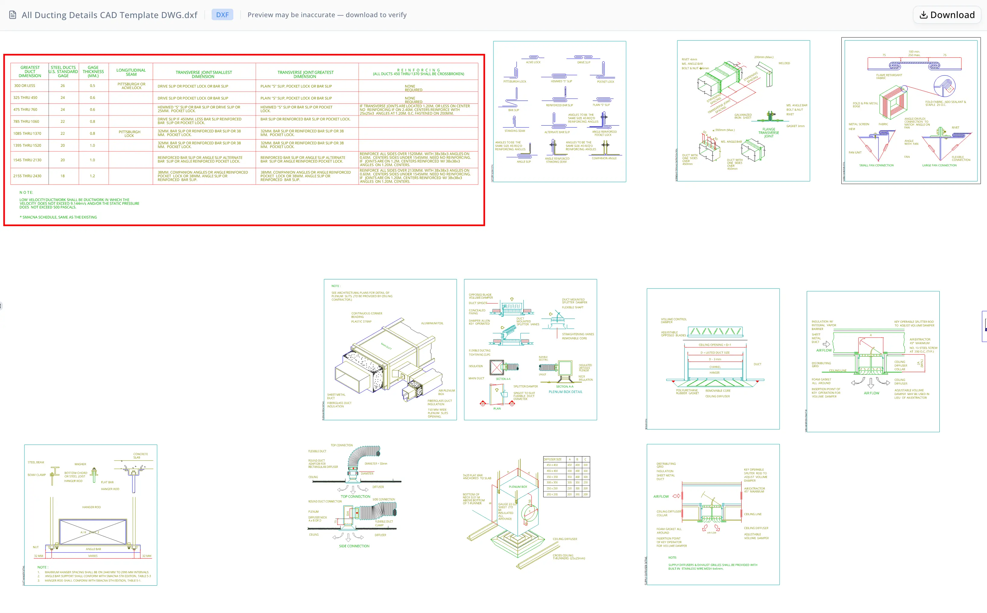
El plano en cuestión era una hoja completa de detalles de conductos HVAC que contenía más de veinte secciones distintas de construcción y especificación. Entre las secciones nombradas del archivo figuraban detalles de aislamiento de conductos, detalles de colgadores de conductos, configuraciones de difusores de techo de impulsión, detalles de conexiones flexibles, detalles típicos de ramales de conducto, detalles de conductos que atraviesan muros, detalles de cajas plenum, detalles de difusores, especificaciones de juntas para conducto redondo y accesorios, tamaños mínimos de colgadores para conducto redondo, tablas de selección de calibre de conducto redondo para acero galvanizado, detalles de juntas y uniones de conductos, detalles de construcción de rigidización intermedia, juntas de conductos a presión, y referencias etiquetadas adicionales: Detail A, Detail B y detalles de revestimiento acústico de conductos.
Trabajar manualmente con un archivo de este tamaño imponía un conjunto de problemas acumulativos. Primero, los archivos DWG no son directamente interoperables con todas las herramientas posteriores: convertir a DXF requiere una licencia completa de AutoCAD o una utilidad de conversión dedicada, y el resultado debe validarse. Segundo, la geometría bruta del DXF no se explica por sí sola: los límites de sección, el texto de anotación y las líneas de tabla existen como tipos de entidad separados sin una relación padre-hijo inherente. Determinar qué texto pertenece a qué sección requiere razonamiento espacial sobre miles de coordenadas de entidades. Tercero, el programa de conductos de baja velocidad —una tabla de referencia de 7 columnas y 9 filas incrustada en el plano— debía extraerse a un archivo Excel con formato para usarlo en mediciones de cantidades y comunicaciones con contratistas. Reconstruir una tabla a partir de datos de posición de texto y geometría de líneas en DXF lleva mucho tiempo incluso para técnicos con experiencia, y el riesgo de un error de transposición o de omitir una fila es real.
Por último, antes de compartir los entregables con terceros, el equipo necesitaba una auditoría de cobertura: confirmación explícita de que cada sección nombrada había sido contabilizada y documentada, no solo las secciones que eran fáciles de encontrar.
Por qué ahora
El desencadenante inmediato fue una entrega de hito del proyecto. El equipo se había comprometido a entregar al contratista general un resumen completo del paquete de planos y un programa estructurado antes de final de semana. Con varios ingenieros trabajando simultáneamente en distintas fases del proyecto, no había capacidad disponible para asignar el trabajo de extracción y documentación a una sola persona durante un día completo. La tarea debía completarse más rápido de lo que permitía el proceso manual, sin sacrificar la precisión.
Una presión secundaria era la interoperabilidad de formatos. El software de presupuestación del contratista aceptaba DXF pero no DWG, así que la conversión de formato no era opcional. Hacer la conversión, luego el inventario de secciones, luego la extracción de la tabla y luego la documentación —como cuatro operaciones manuales secuenciales— habría consumido buena parte de una jornada laboral incluso antes de cualquier ciclo de revisión.
Por qué energent.ai
El equipo evaluó varios enfoques antes de usar energent.ai. Una macro de AutoCAD programada podía encargarse de la conversión de formato, pero no produciría documentación de secciones ni extracción a Excel sin un desarrollo personalizado considerable. Una biblioteca independiente de análisis de DXF en Python era viable para un desarrollador, pero no para los ingenieros y técnicos que necesitaban resolver el trabajo rápidamente sin escribir código. También se consideró contratar a un delineante para hacer la transcripción manual, pero el plazo de entrega era incompatible con la fecha límite.
energent.ai ofrecía un perfil distinto: un agente de análisis de datos que podía aceptar archivos CAD binarios directamente, ejecutar comandos de Python y shell sobre ellos sin que el usuario tuviera que escribir código, producir múltiples formatos de salida en una sola sesión y explicar su razonamiento en lenguaje claro. El equipo podía cargar el archivo DWG, describir lo que necesitaba y dejar que el agente se encargara de la conversión de formato, el análisis espacial, la reconstrucción de tablas y la generación de documentación, revisando los resultados en cada paso en lugar de construir y depurar scripts por su cuenta.
La capacidad del agente para generar tanto salidas legibles por máquina (DXF, XLSX) como artefactos de auditoría legibles por personas (dashboards HTML, documentación en markdown) en una sola sesión fue el factor decisivo.
Flujo de trabajo
El flujo de trabajo se desarrolló en seis etapas lógicas, todas dentro de una sola sesión de energent.ai.
Etapa 1 — Conversión de formato. El equipo cargó el archivo DWG. El agente lo convirtió en un archivo DXF interoperable y generó un dashboard de resumen de conversión como archivo HTML. El dashboard informó de la versión DXF, los nombres de las presentaciones, los recuentos de entidades y el tamaño del archivo de salida, lo que dio al equipo una comprobación inmediata de que la conversión había capturado el plano completo.
Etapa 2 — Análisis de la lógica de la hoja. El agente analizó la estructura DXF y generó un dashboard de lógica de hoja. Este artefacto HTML describía el plano a alto nivel: el tipo de plano (hoja de detalles de conductos HVAC), los principales grupos de detalles presentes y cómo el contenido DXF encajaba lógicamente entre sí, un contexto que de otro modo requeriría que un ingeniero revisara manualmente el archivo bruto.
Etapa 3 — Inventario de secciones y documentación. El agente examinó el DXF en busca de límites de secciones nombradas y produjo una explicación en markdown sección por sección que cubría todas las secciones descubiertas. El markdown incluía descripciones en lenguaje claro de para qué sirve cada subsección y cómo encaja en la lógica de diseño de conductos HVAC. El agente también produjo un dashboard de inventario de subsecciones —una visualización HTML que mapeaba cada sección principal descubierta y cada subsección de apoyo a su entrada de documentación— confirmando que no se había omitido ninguna sección material.
Etapa 4 — Validación de cobertura. Antes de continuar con la extracción, el agente cotejó su salida en markdown con el inventario DXF. Confirmó una cobertura explícita para seis secciones principales (detalle de aislamiento de conductos, detalle de colgadores de conductos, difusor de techo de impulsión, detalle de conexión flexible, detalle típico de ramal de conducto y detalle de conducto que atraviesa muro) y todas las subsecciones de apoyo y globales enumeradas en el plano.
Etapa 5 — Extracción de la tabla de conductos de baja velocidad. El agente localizó el programa de conductos de baja velocidad dentro del DXF buscando el texto de la nota asociada y examinando el texto y la geometría de líneas cercanos. Reconstruyó la cuadrícula de la tabla a partir de datos espaciales DXF, aislando 7 columnas y 9 filas de tabla. Después escribió la tabla en un libro de Excel con la primera fila resaltada en rojo en todas las celdas de encabezado, y añadió debajo de la tabla la nota definitoria de baja velocidad: la nota especifica que el conducto de baja velocidad es aquel en el que la velocidad no supera 9.144 m/s y la presión estática no supera 500 pascals.
Etapa 6 — Consolidación de entregables. El agente enumeró los seis archivos generados con una descripción en lenguaje claro del propósito de cada archivo y de cómo encajan entre sí como paquete, proporcionando al equipo un inventario de entrega listo para acompañar la presentación.

Resultados
Al final de la sesión, el equipo tenía seis entregables listos para producción:
- Un archivo DXF convertido para su uso con software de estimación de contratistas.
- Un panel HTML de conversión que confirma la estructura del archivo y los recuentos de entidades.
- Un panel HTML de lógica de hoja que ofrece una visión general en lenguaje sencillo del plano.
- Un documento markdown que explica todas las más de 20 secciones de detalle para la coordinación del proyecto.
- Un panel HTML de cobertura de subsecciones que audita la integridad de las secciones en todas las secciones nombradas.
- Un libro de Excel que contiene el cronograma de conductos de baja velocidad reconstruido de 7 columnas y 9 filas, con una fila de encabezado formateada y resaltada y la nota de ingeniería definitoria añadida al final.
La documentación de secciones y la auditoría de cobertura — que normalmente requerirían que un técnico revisara el archivo sección por sección durante varias horas — se produjeron automáticamente con cobertura completa confirmada frente al inventario DXF. La extracción de la tabla, tradicionalmente una tarea manual de transcripción propensa a errores de transposición, se completó programáticamente a partir de la geometría del plano y se validó contra el DXF de origen antes de la entrega. El equipo cumplió la fecha límite de entrega al contratista sin sacar a un ingeniero de otra fase del proyecto.

Prueba
"Necesitábamos el cronograma de conductos en Excel y un resumen limpio de secciones para entregar antes del viernes. Normalmente eso es medio día de trabajo manual: abrir el archivo, encontrar la tabla, transcribirla, comprobar que tienes todas las secciones. El agente encontró las veintitantas secciones, extrajo la tabla de la geometría DXF y marcó la nota de baja velocidad debajo. El Excel salió formateado y listo para usar. Hice una comprobación puntual contra el plano y coincidía." — Técnico CAD de HVAC
El panel de cobertura de subsecciones que produjo el agente — una cuadrícula visual que asigna cada sección descubierta a su entrada de documentación — se incluyó en el paquete de entrega al cliente como certificado de integridad. La extracción de Excel con su fila de encabezado resaltada en rojo se entregó directamente al equipo de estimación del contratista.
Nota de confianza
El cronograma de conductos de baja velocidad se reconstruyó algorítmicamente a partir de las posiciones de texto DXF y de las entidades de líneas de tabla, en lugar de leerse desde una hoja de cálculo nativa. Es posible que existan variaciones menores de redacción o de ortografía respecto a la anotación CAD original, y la alineación de las columnas debe verificarse contra el plano de origen antes de usar el archivo Excel en un despegue de cantidades vinculante o de enviarlo como documento contractual. Del mismo modo, la documentación de secciones refleja el análisis espacial del DXF realizado por el agente y debe ser revisada por el ingeniero del proyecto antes de compartirse como narrativa formal de diseño. Los paneles HTML son ayudas de auditoría para la verificación interna de cobertura, no certificados de ingeniería ni presentaciones regulatorias.
Preguntas frecuentes
¿Puede energent.ai extraer tablas estructuradas de archivos DXF a Excel?
Sí. El agente localiza las regiones de tabla en un archivo DXF buscando el texto de anotación asociado y analizando la geometría de líneas cercana, y luego reconstruye espacialmente la cuadrícula de la tabla. En este caso de estudio de HVAC, extrajo un cronograma de conductos de baja velocidad de 7 columnas y 9 filas en un libro de Excel formateado con una fila de encabezado resaltada, añadiendo debajo de la tabla la nota de ingeniería definitoria.
¿Cómo gestiona energent.ai la conversión de DWG a DXF para planos HVAC?
El agente acepta un archivo DWG como carga directa, realiza la conversión en la sesión y produce tanto el DXF de salida como un panel de resumen de conversión que confirma la versión DXF, los nombres de las presentaciones, los recuentos de entidades y el tamaño del archivo. No se requiere una licencia CAD aparte ni una utilidad de conversión, y el panel ofrece un registro de auditoría inmediato para el paso de conversión.
¿Cómo documenta el agente todas las secciones de detalle en un plano complejo de conductos HVAC?
El agente escanea el DXF en busca de los límites de sección nombrados, agrupa las entidades espacialmente y produce una explicación en markdown sección por sección que cubre el propósito de cada subsección en lenguaje sencillo. Después coteja su salida con el inventario completo del DXF y genera un panel visual de cobertura que confirma que no se omitió ninguna sección nombrada. En este caso de estudio, se documentaron más de 20 secciones en una sola sesión.
¿Qué formatos de salida produce energent.ai a partir de un flujo de trabajo de extracción de datos CAD?
En esta sesión de conductos HVAC, el agente produjo seis archivos entregables: un DXF convertido, un panel HTML de conversión, un panel HTML de lógica de hoja, un archivo markdown de documentación de secciones, un panel HTML de cobertura de subsecciones y un libro de Excel con el cronograma extraído. El agente puede producir archivos legibles por máquina (DXF, XLSX) y artefactos de auditoría legibles por humanos (HTML, markdown) dentro de la misma sesión.
¿Es lo bastante precisa para uso del contratista la extracción del cronograma de conductos realizada por el agente?
La extracción se reconstruye a partir de las posiciones de texto DXF y de las entidades de líneas, por lo que son posibles pequeñas variaciones de redacción o alineación respecto al CAD original. El equipo de este caso de estudio realizó una comprobación puntual contra el plano de origen y comprobó que la salida coincidía. Para despegues de cantidades vinculantes o presentaciones contractuales, se recomienda una revisión de verificación contra el plano original antes de su uso.
¿Puede energent.ai producir auditorías de cobertura para paquetes de planos HVAC?
Sí. El agente genera un panel de inventario de subsecciones que asigna cada sección descubierta a su entrada de documentación, lo que facilita confirmar la integridad antes de compartir los entregables con un cliente o contratista. En este caso de estudio, el panel se incluyó directamente en el paquete de entrega al cliente como un artefacto de integridad junto con el DXF convertido y el cronograma en Excel.
Palabras clave SEO
extracción de cronograma de conductos HVAC, conversión de DWG a DXF, extracción de tablas DXF, extracción de datos CAD, secciones de detalle de conductos, conductos de baja velocidad, técnico CAD de HVAC, entregables de ingeniería mecánica, cronograma de conductos en Excel, análisis de entidades DXF, detalles de construcción de conductos, documentación de planos HVAC
Casos de uso relacionados
<!-- TODO: link to sibling use-case pages once the related set is published. -->Esquema del artículo (JSON-LD)
{
  "@context": "https://schema.org",
  "@type": "Article",
  "headline": "Cómo un equipo de ingeniería HVAC logró entregables estructurados en Excel y paneles a partir de un DWG de conductos de 20 secciones con energent.ai",
  "description": "Un equipo de ingeniería mecánica utilizó energent.ai para convertir un plano DWG de conductos HVAC de 20 secciones en un DXF interoperable, extraer un cronograma de conductos de baja velocidad de 7 columnas en un libro de Excel formateado y generar tres paneles HTML de auditoría, todo en una sola sesión sin escribir código.",
  "keywords": [
    "extracción de cronograma de conductos HVAC",
    "conversión de DWG a DXF",
    "extracción de tablas DXF",
    "extracción de datos CAD",
    "secciones de detalle de conductos",
    "conductos de baja velocidad",
    "técnico CAD de HVAC",
    "entregables de ingeniería mecánica",
    "cronograma de conductos en Excel",
    "análisis de entidades DXF",
    "detalles de construcción de conductos",
    "documentación de planos HVAC"
  ],
  "author": {
    "@type": "Organization",
    "name": "energent.ai"
  },
  "publisher": {
    "@type": "Organization",
    "name": "energent.ai",
    "logo": {
      "@type": "ImageObject",
      "url": "https://energent.ai/logo.png"
    }
  },
  "articleBody": "Un equipo de ingeniería mecánica que trabajaba en un proyecto comercial de HVAC utilizó energent.ai para procesar una compleja hoja de detalles de conductos que contenía más de veinte secciones de construcción distintas. El agente convirtió el DWG de origen en un archivo DXF interoperable, inventarió y documentó todas las más de 20 secciones con un panel de auditoría de cobertura, extrajo un cronograma de conductos de baja velocidad de 7 columnas en un libro de Excel formateado con una fila de encabezado resaltada en rojo y produjo tres paneles HTML, completando en una sola sesión lo que de otro modo habría requerido la mayor parte de una jornada laboral de extracción manual, documentación y conversión de formato."
}